Turning an ATX PSU in to a bench supply

While packing up my things to move house I came across an old ATX PSU that I forgot I owned. Rather than putting it in a box and getting on with packing, I figured I'd re-purpose it as a bench supply. There's plenty of write ups on the web about this, but I worked directly from the pinouts on Wikipedia.

Here's what the PSU looked like when I opened it up. As you can see, I have removed a fan from the back (front?) of the unit,  this is where the bench supply outputs will go.

PSU Internals

This is where the fan came from, I've placed a sheet of Sintra board behind the opening (covered with masking tape so it's easy to draw on). Notice the U shaped cut out (top left), this is where the original ATX wiring loom came out, but I'll be using it to mount a switch.

New front panel

Here's the openings marked on the Sintra

Opening outline

Holes cut out for the outputs and switch

Holes cut out

Here is everything fitted to the Sintra panel. The outputs will be wired up as 3.3V on the top left, 5V top right and 12V at the bottom.

Outputs fitted

I have no photos of the wiring as the space to too tight to get any good shots, but it is fairly trivial. Hook the yellow wires up to 12V output, red ones to the 5V output and orange ones to the 3.3V output. Make sure to hook up as many ground wires to each ground output as you have live wires, to ensure maximum current capability. Hook up the green wire to the switch, and ground the other terminal.

Here is the finished product (currently without labelled outputs), notice the addition of an LED between the top outputs. This is just to serve as an obvious indication that the supply is on. I also added the intake hole on top, as removing the 2nd fan was starving the supply of cold air.

20130902_212127

Posted in Uncategorized

Wireless Servo Control - Part 3.1: Failsafe servo control

Since my previous post in this series I have been using the servo control code fairly extensively and have come across a recurring problem. If the application hangs/crashes or is terminated (without termination handling included and working), the output channels simply maintain there previous values. If a channel is connected to a motor controller this could leave the motor running, potentially causing your car/robot/aircraft to run away from you (and in to a wall) at great speed! This is not ideal, therefore, before my final post in the series, I thought I'd include this one on implementing a failsafe in the PRU code.

Here is the complete failsafe PRU code, with the new code highlighted

.origin 0
.entrypoint START
#include "../include/pru.hp"

START:
// Preamble to set up OCP and shared RAM
	LBCO	r0, CONST_PRUCFG, 4, 4		// Enable OCP master port
	CLR 	r0, r0, 4					// Clear SYSCFG[STANDBY_INIT] to enable OCP master port
	SBCO	r0, CONST_PRUCFG, 4, 4
	MOV		r0, 0x00000120				// Configure the programmable pointer register for PRU0 by setting c28_pointer[15:0]
	MOV		r1, CTPPR_0					// field to 0x0120.  This will make C28 point to 0x00012000 (PRU shared RAM).
	ST32	r0, r1
// End of preamble

// Shared memory registers
//	Int 0: 		Total PWM period (number of PRU cycles)
//	Int 1-8:	Pulse width for each channel (number of PRU cycles)
//	Int 9:		Failsafe timeout (number of PWM cycles)
//				e.g. for a PWM frequency of 50Hz, a value of 100 would be a 2s timeout
//				Must be reset everytime channels are updated
//				Set to 0 to disable failsafe feature
//	Int 10-17:	Failsafe PWM periods (number of PRU cycles)
LOOP1:										// Outer loop repeats everything at PWM period
	LBCO	r0, CONST_PRUSHAREDRAM, 0, 40	// Load in registers from shared memory
	QBEQ	NO_FAILSAFE, r9, 0				// Check to see if failsafe is enabled
	QBEQ	FAILSAFE, r9, 1					// Check to see if failsafe timeout has occured
	SUB		r9, r9, 1						// If not timed out, decrement timeout counter
	SBCO	r9, CONST_PRUSHAREDRAM, 36, 4	// Write timeout counter back to shared RAM
	QBA		NO_FAILSAFE						// Skip failsafe action
FAILSAFE:
	LBCO	r1, CONST_PRUSHAREDRAM, 40, 32	// Overwrite commanded positions with failsafe positions

NO_FAILSAFE:
	MOV		r30.b0, 0xFF					// Turn on all output channels for start of cycle

LOOP2:										// Inner loop to handle channels
		SUB		r0, r0, 1					// Subtract one from each register
		SUB		r1, r1, 1
		SUB		r2, r2, 1
		SUB		r3, r3, 1
		SUB		r4, r4, 1
		SUB		r5, r5, 1
		SUB		r6, r6, 1
		SUB		r7, r7, 1
		SUB		r8, r8, 1
		QBNE	SKIP1, r1, 0				// Compare each register with zero
		CLR		r30.t0						// If zero then turn off the corresponding channel
SKIP1:										// Otherwise skip that channel (leaving it high)
		QBNE	SKIP2, r2, 0
		CLR		r30.t1
SKIP2:
		QBNE	SKIP3, r3, 0
		CLR		r30.t2
SKIP3:
		QBNE	SKIP4, r4, 0
		CLR		r30.t3
SKIP4:
		QBNE	SKIP5, r5, 0
		CLR		r30.t4
SKIP5:
		QBNE	SKIP6, r6, 0
		CLR		r30.t5
SKIP6:
		QBNE	SKIP7, r7, 0
		CLR		r30.t6
SKIP7:
		QBNE	SKIP8, r8, 0
		CLR		r30.t7
SKIP8:
		QBEQ	LOOP1, r0, 0			// If cycle register is empty, restart
		QBA		LOOP2					// Total of 19 statements per cycle, 95ns
	HALT								// Halt the processor (although we will never get here...)

  • Lines 37-41 are just some comments about the register values.
  • Line 42 is the start of the PWM cycle, as before.
  • Line 43 reads in one extra value than before, register 9, which corresponds to the number of PWM cycles remaining until the failsafe timeout should be triggered. For example if the PWM frequency is 50Hz, a value of 100 would correspond to a 2s timeout.
  • Line 44 checks to see if the failsafe timeout has been set to zero, indicating the host code wishes to disable the failsafe. If so, the failsafe logic is skipped.
  • Line 45 checks to see if the failsafe timeout has reached 1, indicating that the timeout has occured. If so, the timer logic is skipped and execution skips ahead to load the failsafe values.
  • Lines 46-47 decrement the failsafe counter and save the new value back in to shared RAM. The host code is able to interrogate this register to see how long until the failsafe will be triggered.
  • Line 48 skips over the failsafe as we've not timed out yet.
  • Line 49 is just a label representing the start of the failsafe behaviour.
  • Line 50 loads the failsafe values in to the local registers r1-r8, overwriting the channel values loaded previously (on line 43).
  • (Line 51 is blank)
  • Line 52 is a label for skipping the failsafe.
  • Line 53 sets all the output channels high in (start of PWM cycle) one command. In my previous code I used 8 separate SET instructions to do this, but as I've now introduced additional failsafe instructions at the beginning of a PWM cycle I figured I should optimise this so I don't drift too far from the desired frequency.

I have modified the C++ class to include setFailsafeValue and setFailsafeTimeout methods. In addition, whenever a call to setChannelValue is made, the failsafe timeout register is reset. Including the failsafe functionality in the PRU itself also removes the need for a signal handling code to catch Ctrl+C. The new example code is now a lot simpler, it looks like this

#include "pruPWM.h"

// Entry point
int main() {
	// Initialise PRU PWM
	PRUPWM *myPWM = new PRUPWM();

	// Set Channel 0 failsafe value
	myPWM->setFailsafeValue(0, 1000000);
	
	// Set a 2s failsafe timeout
	myPWM->setFailsafeTimeout(2000);
	
	// Start the PRU
	myPWM->start();

	// An example loop
	int pwm0 = 1000000, pwm7 = 2000000;
	int step = 100;
	while (true) {
		myPWM->setChannelValue(0,pwm0);
		myPWM->setChannelValue(7,pwm7);
		pwm0 += step;
		pwm7 -= step;
		if (pwm0 >= 2000000 || pwm0 <= 1000000 || pwm7 >= 2000000 || pwm7 <= 1000000) {
			step *= -1;
			usleep(1000000);
		}
		usleep(100);
	}
}

This example represents a typical RC aircraft configuration, where channel 0 represents the throttle channel and 1000us is its off position. If the code is halted for any reason, 2s after the last call to setChannelValue the PRU will default all channels to 1500us with the exception of channel 0 which will be set to 1000us.

Some modern RC systems enable more complex failsafes such as keeping some channels at their current value whilst failsafing others. This behavour can be achieved by calling setFailsafeValue whenever setChannelValue is called, for those channels you wish to retain their values.

Posted in BeagleBone Black

Understanding BBB PRU shared memory access

I have previously posted about using the Programmable Realtime Units (PRUs) on the BBB for servo control, and in the PRU code for this I noted that I'd stolen the set up code from the examples provided here. This stolen code enables the PRU OCP ports (enabling communication between the PRUs and the host processor) and sets up the shared memory access. Working with PRU0 this code worked fine, but when I attempted to write code for PRU1 (for an extension to my Wireless Servo Control project), the memory access was not working. After initially suspecting my C++ interface code, I eventually traced this to poorly explained register access by the examples. So I'm writing this post to clear things up for future reference, and to help anyone else who might be stuck!

Example Code Explanation

First, lets have a look at what the example is actually doing. You can refer to my servo control post for the full code, but here is the relevant part.

LBCO    r0, CONST_PRUCFG, 4, 4      // Enable OCP master port
CLR     r0, r0, 4                   // Clear SYSCFG[STANDBY_INIT] to enable OCP master port
SBCO    r0, CONST_PRUCFG, 4, 4
MOV     r0, 0x00000120              // Configure the programmable pointer register for PRU0 by setting c28_pointer[15:0]
MOV     r1, CTPPR_0                 // field to 0x0120.  This will make C28 point to 0x00012000 (PRU shared RAM).
ST32    r0, r1

The comments give you an idea of what is going on, but the details are hidden from view. Two important things to note immediately are the constants CONST_PRUCFG and CTPPR_0 and the macro ST32. These are defined in the header file provided with the examples (this file has various names depending on your source, I call it pru.hp). To both simplify and complicate things, lets replace these with their values (and strip out the comments/shorten the hex)

LBCO    r0, C4, 4, 4
CLR     r0, r0, 4
SBCO    r0, C4, 4, 4
MOV     r0, 0x120
MOV     r1, 0x22028
SBBO    r0, r1, 0, 4

Now this immediately looks more complicated, but at least it is easier to relate to the Reference Guide. Let's look at it in some detail

  • Line 1 uses LBCO to load bytes 4-8 from the register defined by constant C4 in to local register r0. Table 9 on page 25 of the reference guide tells us that the register defined in C4 is PRU-ICSS CFG, the configuration registers for the PRU system. The details of these registers can be found in Section 10 (starting on page 272). Section 10.1.2 tells us that bytes 4-8 are the SYSCFG register.
  • Line 2 clears bit 4 of local register r0. Referring to Section 10.1.2, this is the STANDBY_INIT bit. Clearing this bit disables standby and enables the OCP ports.
  • Line 3 simply writes r0 back to the SYSCFG register, enabling the OCP ports.

At this point you might be thinking this is exactly what the comments said, in a much more concise fashion, and you'd be right! However, this is only because the PRU-ICSS CFG register is common to both PRUs. It's the next part that gets tricky

  • Line 4 simply moves the hex value 0x120 in to local register r0. This will correspond to the value of the c28_pointer bits of the CTPPR0 register.
  • Line 5 moves 0x22028 in to local register r1. This is the address of the CTPPR0 register for PRU0, and this is where all the problems come from. The constant defined previously was named CTPPR_0, and there is another one called CTPPR_1. Surely these are for PRU0 and PRU1, right? No such luck, both PRU0 and PRU1 have both of these registers, and the constants defined in the examples only refer to PRU0.
  • Line 6 simply writes the hex value to the register.

Okay, so we know there is a problem with the register address. But also, where on earth does the value 0x120 come from? Let's figure both of these things out...

CTPPR0 Register Address

The reference guide defines the CTPPR0 register in Section 5.4.8 (page 84) as being at "Offset 28h". Now this is interesting when looking at the hex address above, as it ends in 0x28. Now referring to Table 5 on page 19, we see that the PRU0 control registers start at 0x22000. So there we have it; 0x22028 is the CTPPR0 register for PRU0. Table 5 also informs us that the control registers for PRU1 start on 0x24000, so the CTPPR0 register for 0x24028.

Now we have the address sorted, what about the value.

CTPPR0 Register Value

The reference guide defines the CTPPR0 register as being the Constant Table Programmable Pointer Register 0. It is responsible for setting up the offset of C28 (and C29, which we don't care about) in the constant table. Doing this enables us to use LBCO and SBCO to access memory directly without having to worry about any offsets inside the code.

Referring to the CTPPR0 definition and Table 9 (page 25) we can see that

c28_pointer = CTPPR0[0:15]
nnnn = c28_pointer
C28 = 0x00nnnn00

Therefore, the value 0x120 used above would set C28 to 0x00012000, so what does this mean?

The global memory map is shown in Table 6 (page 20) and identifies 0x00010000 as being the start of the 12Kb of shared memory. Therefore, value of 0x00012000 is somewhere inside the shared memory (albeit not at the beginning). This explains the somewhat arbitrary 2048 offset inside the C code of the examples, as 0x2000 = 4 * 2048, and the C code reads memory as integers (which are 4 bytes wide).

Now we understand what the value means, it would seem to make more sense to set CTPPR0 to 0x100, corresponding to the start of the shared memory. This would also do away with the need for an offset of 2048 in the host code.

Delving a bit deeper in to the memory map lets us find a few more possible values. The default value of 0x000 corresponds to the PRUs own memory space. This means if you don't change anything, C28 will point at each PRUs own memory. Two PRUs running the exact same code would each be using their own memory spaces and wouldn't cause any conflicts. A value of 0x020 corresponds to the memory space of the other PRU, so this could be used as a form of inter-PRU communication (or just use the shared space).

Some new set up code

Now we've got our head around everything, lets define some more convenient set up code

// Put this in a header file
#define CONST_PRUCFG         C4
#define CONST_PRUSHAREDRAM   C28

#define PRU0_CTRL            0x22000
#define PRU1_CTRL            0x24000

#define CTPPR0               0x28

#define OWN_RAM              0x000
#define OTHER_RAM            0x020
#define SHARED_RAM           0x100

// Start your code with this
LBCO    r0, CONST_PRUCFG, 4, 4          // Enable OCP master port
CLR     r0, r0, 4
SBCO    r0, CONST_PRUCFG, 4, 4
MOV     r0, SHARED_RAM                  // Set C28 to point to shared RAM
MOV     r1, PRU1_CTRL + CTPPR0
SBBO    r0, r1, 0, 4

// Do something useful with memory

I have defined some new constants to make everything much easier to follow, namely PRU0_CTRL and PRU1_CTRL which refer to the base of each PRUs control register. I have then modified the CTPPR0 constant to refer to the offset, not an absolute value. In addition, I have included the three most useful values for the c28_pointer bits of the CTPPR0 register, OWN_RAM, OTHER_RAM and SHARED_RAM.

This set up example is similar to the previous one except it uses the start of the shared memory without the offset of 2048 integers. If you wanted to maintain this offset (as I am currently doing for legacy reasons, until I update my C++ class) you could simply add it to line 18

MOV     r0, SHARED_RAM + 0x020
Posted in BeagleBone Black

Wireless Servo Control - Part 3: PWM servo control with the BBB PRU

The previous post in this series detailed the use of the RFM22B wireless transceivers with the BeagleBone Black (BBB). This achieves the "Wireless" part of the title, now to look at the "Servo Control" part.  This post looks at using the BBBs Programmable Realtime Unit (PRU) to generate high resolution Pulse Width Modulation (PWM) signals which can be used to drive servos. For those of you not familiar with PWM servo signals, this Wikipedia page gives a basic introduction.

Enabling the PRU

Enabling the PRU system on the BBB is a little convoluted. A kernel driver already exists (uio_pruss), but this needs to be supplemented with a userspace driver which must be built from source. The PRU is coded in TIs own assembly instruction set, therefore the assembler must also be built from source. I have hidden the details of all of this inside a convenient bash script, feel free to have a look inside if you want to know the details. Firstly, grab my git repository

git clone https://github.com/omcaree/bbb-prupwm.git
cd bbb-prupwm

Now, do all the of setup with

sudo ./install_pruss.sh

You might see a few warnings which you can safely ignore, but any errors would be bad. Assuming everything went okay, we can now sort out the device tree.

I have included a device tree overlay which enables the PRU and enables all of the available PRU0 outputs (the BBB has 2 PRUs, we will only use PRU0 for this post). Before we install this, lets look at what it does.

The BBB SRM doesn't show the PRU modes for header pins, therefore to identify the output pins refer to my spreadsheet. Signals identified as pr1_pru0_pru_r30_* are outputs for PRU0 (and those identified as pr1_pru0_pru_r31_* are inputs, the naming convention will make a little more sense later). Inspection of the spreadsheet reveals the following outputs available.

PRU0 Output pins
Signal Pin Mode DT Offset Pin mux value
pr1_pru0_pru_r30_0 P9_31 5 0x190 0x05
pr1_pru0_pru_r30_1 P9_29 5 0x194 0x05
pr1_pru0_pru_r30_2 P9_30 5 0x198 0x05
pr1_pru0_pru_r30_3 P9_28 5 0x19C 0x05
pr1_pru0_pru_r30_4 P9_42* 5 0x1A0 0x05
pr1_pru0_pru_r30_5 P9_27 5 0x1A4 0x05
pr1_pru0_pru_r30_6 P9_41* 5 0x1A8 0x05
pr1_pru0_pru_r30_7 P9_25 5 0x1AC 0x05
pr1_pru0_pru_r30_14 P8_12 6 0x30 0x06
pr1_pru0_pru_r30_15 P8_11 6 0x34 0x06

*These pins are each connected to two signals, which ever signal is not being used (offsets 0x1B4 and 0x164) must be set as inputs (0x20).

The pin mux values are simply the pin mode, settings such as slew rate and pull up/down are left default. You can confirm this with the register value worksheet in the spreadsheet. The overlay pin mux is therefore

0x030 0x06  /* P8_12 to PRU output */
0x034 0x06  /* P8_11 to PRU output */
0x190 0x05  /* P9_31 to PRU output */
0x194 0x05  /* P9_29 to PRU output */
0x198 0x05  /* P9_30 to PRU output */
0x19C 0x05  /* P9_28 to PRU output */
0x1A0 0x05  /* P9_42 to PRU output */
0x1A4 0x05  /* P9_27 to PRU output */
0x1A8 0x05  /* P9_41 to PRU output */
0x1AC 0x05  /* P9_25 to PRU output */
0x1B4 0x20  /* CLKOUT2 to input as per datasheet (to enable P9_41) */
0x164 0x20  /* GPIO0_7 to input as per datasheet (to enable P9_42) */

If you're running Ubuntu, before compiling the overlay, make sure you have the patched device tree compiler. To compile, install and enable this overlay all at once, simply run

sudo ./enable_pru0_outputs.sh

PWM with the PRU

Now your BBB PRU should be set up an ready to use, so lets have a look at programming the PRU to do PWM. Note that I'm only using the 8 outputs on the P9 header for PWM, despite enabling them all in the overlay (two additional outputs exist on P8).

I should start by saying I taught myself the basics of TI's PRU assembly instruction set fairly quickly and didn't bother with macros and things, because I knew my code was going to be fairly short. I don't doubt there are far better ways of coding this, but it works which is all I want. We'll look at the PRU code first (since that's the interesting bit), then we'll look at how we run and interact with it.

PRU Code

.origin 0
.entrypoint START
#include "../include/pru.hp"

START:
// Preamble to set up OCP and shared RAM
	LBCO	r0, CONST_PRUCFG, 4, 4		// Enable OCP master port
	CLR 	r0, r0, 4					// Clear SYSCFG[STANDBY_INIT] to enable OCP master port
	SBCO	r0, CONST_PRUCFG, 4, 4
	MOV		r0, 0x00000120				// Configure the programmable pointer register for PRU0 by setting c28_pointer[15:0]
	MOV		r1, CTPPR_0					// field to 0x0120.  This will make C28 point to 0x00012000 (PRU shared RAM).
	ST32	r0, r1
// End of preamble

// Shared memory registers
//	Int 0: 		Total PWM period (number of PRU cycles)
//	Int 1-8:	Pulse width for each channel (number of PRU cycles)
LOOP1:										// Outer loop repeats everything at PWM period
	LBCO	r0, CONST_PRUSHAREDRAM, 0, 36	// Load in registers from shared memory
	SET		r30.t0							// Turn on all output channels for start of cycle
	SET		r30.t1
	SET		r30.t2
	SET		r30.t3
	SET		r30.t4
	SET		r30.t5
	SET		r30.t6
	SET		r30.t7
LOOP2:										// Inner loop to handle channels
		SUB		r0, r0, 1					// Subtract one from each register
		SUB		r1, r1, 1
		SUB		r2, r2, 1
		SUB		r3, r3, 1
		SUB		r4, r4, 1
		SUB		r5, r5, 1
		SUB		r6, r6, 1
		SUB		r7, r7, 1
		SUB		r8, r8, 1
		QBNE	SKIP1, r1, 0				// Compare each register with zero
		CLR		r30.t0						// If zero then turn off the corresponding channel
SKIP1:										// Otherwise skip that channel (leaving it high)
		QBNE	SKIP2, r2, 0
		CLR		r30.t1
SKIP2:
		QBNE	SKIP3, r3, 0
		CLR		r30.t2
SKIP3:
		QBNE	SKIP4, r4, 0
		CLR		r30.t3
SKIP4:
		QBNE	SKIP5, r5, 0
		CLR		r30.t4
SKIP5:
		QBNE	SKIP6, r6, 0
		CLR		r30.t5
SKIP6:
		QBNE	SKIP7, r7, 0
		CLR		r30.t6
SKIP7:
		QBNE	SKIP8, r8, 0
		CLR		r30.t7
SKIP8:
		QBEQ	LOOP1, r0, 0			// If cycle register is empty, restart
		QBA		LOOP2					// Total of 19 statements per cycle, 95ns
	HALT								// Halt the processor (although we will never get here...)
  • Lines 20-32 are shamelessly stolen from the example codes packaged with the drivers. They deal with setting up the PRU memory and interrupts
  • Line 37 defines the start of the useful code, it is a label identifying the top of the main loop (imaginatively named LOOP1). This loop is responsible for repeating the PWM pulses at a fixed frequency
  • Line 38 uses LBCO to load 9 4-byte registers (36 bytes) from shared memory in to the PRUs internal registers (r0-r8). These registers represent the total PWM period and the period of the 8 output channels (all of which are in units of PRU cycles, more on this later)
  • Lines 39-46 use SET to set the individual bits of register r30 high to start the PWM signal. These bits correspond directly to the output pins identified earlier (e.g. setting the r30.t0 toggles the pr1_pru0_pru_r30_0 signal high). This could be done with a single operation (setting r30 to 0b11111111), but I opted to be verbose to make things easier to follow/debug.
  • Line 47 starts another loop which handles the setting of outputs low when their periods have elapsed.
  • Lines 48-56 use SUB to decrement each of the period registers by 1
  • Lines 57-80 perform the same comparison operation on all channels. Firstly QBNE is used to branch to label SKIPx if register rx is not equal to 0, otherwise execution simply continues and invokes CLR to set the corresponding output register bit low (that is, its period has elapsed). The net effect (for channel 1) of this is identical to an if statement:
if (r1 == 0) {
     clear(r30.t0);
}
  • Line 81 uses QBEQ to start the next PWM pulse (from LOOP1) when the total PWM period has elapsed (i.e. r0 == 0) .
  • Line 82 continues the current PWM pulse indefinitely (from LOOP2) with QBA. This statement is only reached if the previous QBEQ is not executed (therefore we continue the current pulse if we haven't already reset for the next pulse).
  • Line 83 halts the PRU, but this statement is never actually reached because the QBA above will always branch to LOOP2

PRU Timing

The above description spent a lot of time referring to PWM and channel periods, I should probably explain this in more detail. The PRU has limited mathematical capabilities (unless you code them yourself), so you want to offload as much calculation as possible to the host process. For PWM generation, this means you don't pass the PRU parameters such as pulse time (e.g. 1500us), frequency (e.g. 50Hz) or duty cycle (e.g. 20%), because all of these require multiplication or division operations to arrive at a number of loops value. Instead, we simply pass the PRU this number of loops directly. To calculate this value, the host process needs to know how long it takes the PRU to execute a single loop. Being a realtime unit, independent of the CPU, we can calculate this loop time by multiplying the number of statements by the time it takes to execute a single statement.

To determine the number of statements, we first ignore the conditional statements which are usually skipped (the clearing of output bits). This will introduce a minor inaccuracy in our timing, but as these statements only execute 8 times (once per channel) in tens of thousands of loops, it's a minor effect. Next we count up the remaining statements executed within the inner loop (between LOOP2 on line 47 and QBA on line 82). The counted statements are highlighted in the listing above, 19 statements in total. Each statement takes a single clock cycle to execute and the PRU clock is 200MHz, therefore the time taken to execute a single PRU cycle is

 19 \times \frac{1}{200MHz} = 19 \times 5ns = 95ns

To generate a 50Hz signal (for standard RC servos), the PRU PWM period register (r0) should be set to

 \frac{1}{50Hz} \frac{1}{95ns} = \frac{0.02s}{95\times10^{-9}s} = 210526

And to set the first channel to 1500us (centre position of standard servo), the channel period register (r1) should be set to

 \frac{1500\times10^{-6}s}{95\times10^{-9}s} = 15789

Now we have the PRU code and know how to calculate its register values.

Running the example

I've written some C++ classes for interfacing with the PRU (src/pru.cpp and include/pru.cpp) and handling the PWM calculations (src/pruPWM.cpp and include/pruPWM.cpp).

The PRU class is largely based on the example codes bundled with the drivers. It uses the functions from the prussdrv library to set up the PRU, run code and interact with the shared memory. It does not currently support host or PRU interrupts, but I'm working on this for another project.

The PRUPWM class handles the calculation of PWM periods as mentioned above and passes them on to the PRU class.

Here is the example code from the repository, it demonstrates the use of the PRUPWM class to control the channels.

#include <signal.h>
#include "pruPWM.h"

// Some globals
PRUPWM *myPWM;
bool running;

// Default all channels (handy way of quitting with known output state)
void setDefaults(int signal = 0) {
	for (int i = 0; i < 8; i++) {
		myPWM->setChannelValue(i,1500000);
	}
	running = false;
}

// Entry point
int main() {
	// Initialise PRU PWM
	myPWM = new PRUPWM();

	// Default all channels
	setDefaults();

	// Register 'setDefaults' as interrupt handler to catch Ctrl+C
	signal(SIGINT, setDefaults);

	// Start the PRU
	myPWM->start();

	// An example loop
	running = true;
	int pwm0 = 1000000, pwm7 = 2000000;
	int step = 100;
	while (running) {
		myPWM->setChannelValue(0,pwm0);
		myPWM->setChannelValue(7,pwm7);
		pwm0 += step;
		pwm7 -= step;
		if (pwm0 >= 2000000 || pwm0 <= 1000000 || pwm7 >= 2000000 || pwm7 <= 1000000) {
			step *= -1;
			usleep(1000000);
		}
		usleep(100);
	}
}
  • Lines 29-34 is a useful little function to default all the outputs to 1500us (note that setChannelValue takes its argument in ns)
  • Line 39 initialises the class. The constructor takes an optional argument which is the PWM frequency in Hz (50 is default)
  • Line 42 defaults all the channels (do this before starting the PRU or bad things might happen to your servos!)
  • Line 45 registers the setDefault function to be called when Ctrl+C is pressed
  • Line 48 starts the PRU code
  • Lines 51-64 cycles channel 0 and channel 7 up and down (in opposite directions), pausing at the extents

To build the example simply run

make

In addition to compiling the example code, make will use the PRU assembler we built and installed earlier (automatically) to compile the PRU code to pwm.bin, This PRU binary must reside in the same folder as the executable or you'll get a seg fault.

All PRU related code must be run with root privileges in order to access the PRU device and memory space. So run the example with

sudo ./prupwm

Here is a video of the example in action...

Some of you may be wondering how I'm able to drive 5V servos with 3.3V PWM signals. It turns out that the vast majority of 5V devices are perfectly happy with 3.3V signals as they tend to recognise a transition from low to high (and vice versa) at around 2.5V. If I was going to make a product out of this, I would go to the effort of shifting the levels up to 5V as this will provide greater robustness to noise. But for this little prototype it works just fine. Note that I said 5V devices are happy with 3.3V signals, the reverse of this is usually not the case, do not connect 5V signals directly to your BBB or you'll damage it!

Before the next (and final) installment, I have included an update to this post concerning the implementation of a failsafe within the PRU code. The final installment (coming soon...) will use the BBB ADCs to generate the position command for the servos, send this wirelessly using the RFM22Bs and then control the servos on a second BBB, thus achieving the goal of wireless servo control!

Posted in BeagleBone Black

BeagleBone Black Pin Mux Spreadsheet

I'm sure this exists on the web somewhere, but after 30s of Googling I couldn't find it, so I've put together a comprehensive spreadsheet for BBB pinmuxing.

Firstly, I have updated Tables 10 and 11 from the BBB SRM to include:

  • All pin modes from the AM335x Datasheet (SRM doesn't show PRU modes)
  • Colour coded modes depending on whether they are Input, Output or I/O
  • Included the Device Tree Offset values needed for creating pin muxes in a Device Tree Overlay

Note that I have kept the pin names consistent with the SRM, despite this being at odds with the datasheet!

Here are some images of the tables for quick reference

P8 HeaderP8 Header P9 HeaderP9 Header

I've also included a sheet which lets you calculate the required register value for pin muxing.

Spreadsheet is available to download here.

Posted in BeagleBone Black

Wireless Servo Control - Part 2: RFM22B set up

In my previous post I introduced the problem of wireless servo control using a pair of BeagleBone Blacks (BBBs) and RFM22B transceivers. In this post I'll talk about getting the RFM22B working with the BBB and how to set up a simple link between two of them. I am using a pair of 868MHz modules in the DIP package, available here. My BBBs are running the latest Ubuntu image (2013-07-22) with the patched device tree compiler, but this should all work equally well under Angstrom.

Hardware

You shouldn't power on these modules without an antenna attached (particular at higher power settings), so first order of business is to create a pair of antennae. To get things up and running a simple quarter wave wire antenna will do. I plan on using a centre frequency of around 869.5MHz, so the length of wire needed is

 \frac{1}{4}\frac{c}{869.5 \times 10^{6}} = 0.0863m

where c = 3 \times 10^8 is the speed of light in m/s. After soldering on the wires, I put them in a little plastic tube to protect them and keep them straight.

RFM22B Wire Antennae Attaching antennae RFM22B to BBB Hooking up to BBB

With antennae attached we can go ahead and hook the RFM22Bs up to the BBBs. The pin spacing on the RFM22Bs is 2mm rather than the standard 2.54mm (0.1") so I bought some 7x2 2mm spaced crimp connectors to hook them up.

Here is the wiring detail (to SPI0 on the BBB), the RFM22B doesn't have clearly defined pin numbers so I'll use the names given in the datasheet.

RFM22B pin BBB pin
GND P9_1
VCC P9_3
SDO P9_21
SDI P9_18
SCK P9_22
NSEL P9_17

A few pins on the RFM22B need to be hooked up to each other as well.

RFM22B pin RFM22B pin
TX_ANT GPIO_0
RX_ANT GPIO_1
SDN GND

This ties the shutdown pin (SDN) to ground, ensuring the device remains on. If this is left floating the device randomly resets during use which causes all manner of strange behavior! The antenna selection pins (TX_ANT and RX_ANT) will be discussed in more detail later, for now just hook them up as above. That's it for the hardware set up, now to look at the software.

Software

Enable SPI with the device tree

As with all things BBB, the first issue to overcome is the dreaded device tree overlay. Looking in to /lib/firmware gives you some initial false hope

ls /lib/firmware | grep SPI0
BB-SPI0-00A0.dtbo

Loading this overlay didn't have any effect for me. The desired effect being the appearance of a /dev/spidev* node. After some googling, I came across the elinux.org wiki page which gives a working SPI0 overlay.

/dts-v1/;
/plugin/;

/ {
    compatible = "ti,beaglebone", "ti,beaglebone-black";

    /* identification */
    part-number = "spi0pinmux";

    fragment@0 {
        target = <&am33xx_pinmux>;
        __overlay__ {
            spi0_pins_s0: spi0_pins_s0 {
                pinctrl-single,pins = <
                    0x150 0x30  /* spi0_sclk, INPUT_PULLUP | MODE0 */
                    0x154 0x30  /* spi0_d0, INPUT_PULLUP | MODE0 */
                    0x158 0x10  /* spi0_d1, OUTPUT_PULLUP | MODE0 */
                    0x15c 0x10  /* spi0_cs0, OUTPUT_PULLUP | MODE0 */
                >;
            };
        };
    };

    fragment@1 {
        target = <&spi0>;
        __overlay__ {
             #address-cells = ;
             #size-cells = ;

             status = "okay";
             pinctrl-names = "default";
             pinctrl-0 = <&spi0_pins_s0>;

             spidev@0 {
                 spi-max-frequency = ;
                 reg = ;
                 compatible = "linux,spidev";
            };
        };
    };
};

Save this as BB-SPI0-01-00A0.dts, then compile and install with

dtc -O dtb -o BB-SPI0-01-00A0.dtbo -b 0 -@ BB-SPI0-01-00A0.dts
sudo cp BB-SPI0-01-00A0.dtbo /lib/firmware/

Load the overlay with (must be run as root, sudo does not work!)

echo BB-SPI0-01 > /sys/devices/bone_capemgr.*/slots

And the /dev/spidev1:0 node appears!

C++ Example

I was initially planning to prototype everything in Node.JS, but since I couldn't get the SPI plugin to actually do anything I just went straight to C++. All the code is available on GitHub.

I wrote a basic SPI class (see include/spi.h and src/spi.cpp) which lets you control the speed of the bus and transfer data. For those not familiar with SPI (which I wasn't when I started this), the transfer process is a little strange. Sending data requires you to specify both a transmit and receive buffer of equal lengths. The transmit buffer gets sent and the receive buffer goes unused. Receiving data also requires transmit and receive buffers of equal length. The first part of the transmit buffer contains the register you want to read (similar to I2C devices), but the rest of the buffer must be zero filled. The receive buffer gets populated during the transfer, starting at the byte immediately preceding the last non zero byte in the transmit buffer.

For example, to receive 8 bytes (1,2,3,4,5,6,7,8) from register 0x30 you would have a transmit buffer equal to

 0x30 0x00 0x00 0x00 0x00 0x00 0x00 0x00 0x00 

After the transfer, the receive buffer would be

 0x00 0x01 0x02 0x03 0x04 0x05 0x06 0x07 0x08 

Notice that both buffers are 9 bytes long, one for the register and eight for the data.

Thinking about this now (the joy of hindsight), you can probably use the same buffer for sending and receiving since there is no overlap. Note to self, try this out!

The RFM22B (and probably other SPI devices), uses 7 bit registers with the 8th bit used to identify a read or write operation (0 - read, 1 - write).

The RFM22B class (include/rfm22b.h, include/rfm22b_enums.h and src/rfm22b.cpp) contains functions for getting and setting the majority of parameters explained in the datasheet. These include:

  • setCarrierFrequency - sets the carrier frequency in Hertz
  • setDataRate - sets the data rate in bps
  • setTransmissionPower - you get the idea...

Functions which handle sending and receiving of data packets are also included.

There is a simple send/receive example (rfm22b_send_test.cpp and rfm22b_receive_test.cpp) which I'll go through here in detail.

#include "rfm22b.h"

int main() {
	// Initialise the radio
	RFM22B *myRadio = new RFM22B("/dev/spidev1.0");

	// Set the bus speed
	myRadio->setMaxSpeedHz(200000);

	// Radio configuration
	myRadio->reset();
	myRadio->setCarrierFrequency(869.5E6);
	myRadio->setModulationType(RFM22B::GFSK);
	myRadio->setModulationDataSource(RFM22B::FIFO);
	myRadio->setDataClockConfiguration(RFM22B::NONE);
	myRadio->setTransmissionPower(5);
	myRadio->setGPIOFunction(RFM22B::GPIO0, RFM22B::TX_STATE);
	myRadio->setGPIOFunction(RFM22B::GPIO1, RFM22B::RX_STATE);

	// What header are we broadcasting
	myRadio->setTransmitHeader(123456789);

	char output[RFM22B::MAX_PACKET_LENGTH] = "Hello World!";
	printf("Sending '%s'\n", output);
	myRadio->send((uint8_t*)output, RFM22B::MAX_PACKET_LENGTH);
	myRadio->close();
}
  • Line 5 - Creates a new instance of the class, telling it which SPI port to look at
  • Line 8 - Sets the speed of the SPI bus to 200kHz (RFM22B works up to 10MHz, 200kHz was just an arbitrary value)
  • Line 11 - Resets all the registers of the RFM22B to their default states
  • Line 12 - Sets the carrier frequency to 869.5MHz
  • Line 13 - Sets the FM modulation type to GFSK
  • Line 14 - Sets the data source to the RFM22B's internal FIFO (see below)
  • Line 15 - Sets the data clock configuration to nothing (not needed for FIFO)
  • Line 16 - Sets the transmission power to 5dBm
  • Lines 17-18 - Sets the GPIO functions (see below)
  • Line 21 - Sets the header we are broadcasting (see below)
  • Lines 23-25 - Send "Hello World"
  • Line 26 - Closes the device

The RFM22B has a 64 byte FIFO which is the easiest way of using the device. For sending, a buffer is written in to the FIFO register then the device is set to transmit mode. The device then transmits the data and clears the FIFO. For receiving, you place the device in to receive mode and it fills the buffer when a packet is received.

The GPIOs on the RFM22B can be configured in a number of ways. To simplify the connection to the BBB, you should use the GPIOs to switch antenna in to transmit or receive mode as required, these were connected earlier on. If you choose not to do this, you need to hook the TX_ANT and RX_ANT pins up to GPIOs on the BBB and toggle them appropriately from your code.

The RFM22B has a packet handler which is enabled by default and enables you to perform basic authentication of incoming data. To make use of this you should set the transmit header to something unique before sending any data, and set the corresponding check header on the receiver.

The receive code is largely identical, until the last few lines.

#include "rfm22b.h"

int main() {
	// Initialise the radio
	RFM22B *myRadio = new RFM22B("/dev/spidev1.0");

	// Set the bus speed
	myRadio->setMaxSpeedHz(200000);

	// Radio configuration
	myRadio->reset();
	myRadio->setCarrierFrequency(869.5E6);
	myRadio->setModulationType(RFM22B::GFSK);
	myRadio->setModulationDataSource(RFM22B::FIFO);
	myRadio->setDataClockConfiguration(RFM22B::NONE);
	myRadio->setTransmissionPower(5);
	myRadio->setGPIOFunction(RFM22B::GPIO0, RFM22B::TX_STATE);
	myRadio->setGPIOFunction(RFM22B::GPIO1, RFM22B::RX_STATE);

	// What header do we want?
	myRadio->setCheckHeader(123456789);

	// Listen for a packet
	printf("Listening to a message...\n");

	char input[RFM22B::MAX_PACKET_LENGTH];
	myRadio->receive((uint8_t*)input,RFM22B::MAX_PACKET_LENGTH);
	printf("%s\n", input);

	myRadio->close();
}

You can get hold of, and build the examples with

git clone https://github.com/omcaree/rfm22b
cd rfm22b
make

Run the receive code first as this will block until something is received. Then (on another BBB, obviously), run the sending code, you should see this

./rfm22b_receive_test
Listening to a message...
./rfm22b_send_test
Sending 'Hello World!'
Hello World!

A note on Automatic Frequency Control (AFC)

I said above that the RFM22B class has setters for the majority of parameters. It does not, however, (yet) have setters for AFC. AFC is used when receiving to cater for differences in the source clocks of the transmitter and receiver and its parameters must be updated whenever the modulation type, frequency deviation or data rate are changed.

In the examples above, I didn't change the data rate, deviation or modulation type (strictly speaking I did, as the default modulation is unmodulated, but the default AFC values are for GFSK), so I didn't have to worry about AFC. If you wish to modify these then you'll need to get hold of the RFM22B Register Settings Spreadsheet and set the registers manually. Here is an example of some AFC settings for a 57.6kbps data rate with 30kHz deviation.

        // Set deviation
        myRadio->setFrequencyDeviation(30000);

        // Set data rate
        myRadio->setDataRate(57600);
	
        // Receiver AFC settings determined from RFM22B Spreadsheet
        myRadio->setRegister(0x1C, 0x06);
        myRadio->setRegister(0x20, 0x45);
        myRadio->setRegister(0x21, 0x01);
        myRadio->setRegister(0x22, 0xD7);
        myRadio->setRegister(0x23, 0xDC);
        myRadio->setRegister(0x24, 0x07);
        myRadio->setRegister(0x25, 0x22);
        myRadio->setRegister(0x1D, 0x40);
        myRadio->setRegister(0x1E, 0x0A);
        myRadio->setRegister(0x2A, 0x2D);
        myRadio->setRegister(0x1F, 0x03);
        myRadio->setRegister(0x69, 0x60);

Once I've had time to reverse engineer the spreadsheet, I will modify the RFM22B class to automatically set the AFC registers whenever data rate, deviation or modulation are modified.

This post has covered the basics of interfacing an RFM22B transceiver with a BBB. In my next post I discuss the use of the Programmable Realtime Unit (PRU) on the BBB to generate high resolution PWM servo control signals.

Posted in BeagleBone Black

Wireless Servo Control - Part 1: Introduction

Anyone who has played around with Remote Control (RC) toys is familiar with the concept of wireless servo control. A hand held transmitter broadcasts the positions of a couple of thumb joysticks and some switches to a receiver which tells some small motors (servos) what position to move to. These commercially available RC systems are perfectly well suited to controlling everything from small toys right up to massive scale models. Unfortunately, for a lot of robotics projects they are not ideal. Here are a few reasons why:

  • Data transmission is usually one way, meaning you can't get any data back from your vehicle. Modern systems do offer limited telemetry capability but it is far from perfect.
  • Only a small number of servos can be controlled. 12 channel systems are available but are fairly costly.
  • Almost all systems work on the 2.4GHz band. Using Wifi at the same time (for example, to stream video), can cause catastrophic interference.
  • The transmitter is a human interface device, sending commands from a computer requires 3rd party hardware/software which doesn't always work reliably.

The OpenLRS project goes some way to solve these issues. It replaces the radio unit inside a conventional RC transmitter and shifts the frequency to 433MHz (which can be nudged to 459MHz in the UK). This is primarily to increase the range of the system (lower frequencies go further for the same power), but it has the added advantage of removing the interference potential with Wifi. OpenLRS is also based on an Arduino core and features bidirectional transceivers, so it can be reprogrammed to offer telemetry and a serial port interface to a computer.

After using OpenLRS for a while to control a small Unmanned Aircraft System (UAS), a thought occurred to me. Most of our UAS operation requires a computer on both ends of the link, wouldn't it be nice if this computer could handle the communication itself, rather than having to connect to OpenLRS?

Those of you with some experience in wireless telemetry may ask what is wrong with ZigBee systems such as XBee. Being based in the UK means means only the 2.4GHz XBee's are any use (900MHz isn't allowed), so whilst they solve most of the problems the interference issue still exists.

Taking inspiration from OpenLRS, I got hold of a pair of HopeRF RFM22B radio modules and hooked them up to a pair of BeagleBone Blacks (BBBs) via SPI. After a couple of weeks of coding and tweaking I have successfully achieved wireless servo control, here's a (poorly filmed) video to prove it

(The USB cables connected to the BBBs are just so I can control them from the PC, no servo control signals are sent down these I promise! And I've no idea why the audio and video are out of sync)

Over the next few days I'll be posting the details of this project, but here's the highlights. The potentiometer from an old (broken) servo is used to drive one of the BBBs ADCs. This ADC voltage is read by the first BBB and transmitted from one RFM22B to the other. The second BBB receives the voltage and commands the servos appropriately. The PWM signals for servo control are achieved with the BBBs Programmable Realtime Units (PRUs) so as to obtain 8 high resolution channels.

Part 2 of this guide covers hooking up the RFM22Bs to the BBBs and sending a basic "Hello World!" message.

Posted in BeagleBone Black

Introduction and New Logo

Welcome to Embedded Things, the place for all sorts of information about putting embedded systems in things (which usually don't need them). Hardware hacks, software tricks and all sorts of projects will be appearing over the coming weeks, months and years.

My name is Owen and I've been working in the field of small Unmanned Aerial Systems (UAS) research for a few years now. This has given me exposure to all manner of embedded hardware and software. I'm about to change careers, so thought it was time to start documenting some of the things I've learnt along the way for the benefit of mankind. I've started this blog (which is a word I can't stand, by the way) as a place to share the projects I've been working on, hopefully stirring the interest of others along the way.

Once up and running I immediately set to work thinking up content, completely neglecting aesthetics. WordPress took care of the basics, so what more is there to do? Well, after a chance conversation with a friend it was decided that every blog needs a logo. So after "5 minutes" (read: 3 hours) of tinkering, he presented me with his creation (it's at the top of the page, if you haven't figured this out already). It is a much more professional looking job than anything I could have knocked up, and is a great improvement over the previous text heading, thanks Will!

So that's that; blog created, logo uploaded, now to start posting things to benefit mankind...

Posted in Uncategorized

Patching the Device Tree Compiler for Ubuntu

 dtc: invalid option -- '@' 

This is an error familiar to anyone trying to compile device tree overlays for the BeagleBone Black (BBB) on the latest Ubuntu image (2013-07-22). These overlays are required to enable the various devices on board, such as the CANBus in my previous post.

There are plenty of places out there which direct you to Robert C Nelsons Script for building the patched version. But for some reason or other this does not work for me. It gets as far as fetching the dtc source files, but does not patch them or compile/install anything. So if anyone else is having similar troubles, here is how to do it manually (from the comments here).

Firstly, install the packages needed to build the dtc binary.

sudo apt-get install build-essential bison flex

Grab the dtc source code

git clone http://jdl.com/software/dtc.git/
cd dtc

Go to the specific state which the patch is for

git reset --hard f8cb5dd94903a5cfa1609695328b8f1d5557367f

Grab the patch

wget https://patchwork.kernel.org/patch/1934471/raw/ -O dynamic-symbols.patch

Apply the patch

git apply dynamic-symbols.patch

Now build and install dtc

make
sudo cp dtc /usr/local/bin

Now you should be able to compile device tree overlays with the following prototype

dtc -O dtb -o <overlay filename> -b 0 -@ <source filename>
Posted in BeagleBone Black

Enable CANBus on the BeagleBone Black

A few months back I got hold of my first BeagleBone Black (BBB) with the intention of installing it in my car as a trackday data logger. First step in this endeavor was to get the CANBus working. I wrote this up here, but I'm shutting down that (poorly designed) site and have come up with a better way of enabling CAN so here goes.

First up, I'm assuming you are either running the latest Angstrom image (see here), or Ubuntu with the patched device tree compiler (see here). This ensures you have a device tree compiler which is capable of compiling overlays. So with that out of the way...

Enabling DCAN1

Update 26th August 2013: This original post focused on enabling dcan1, as these pins are available by default. If you'd like to enable dcan0 (At the expense of i2c2, possibly breaking any capes you have plugged in!), skip to the bottom of the post

To enable CAN (specifically dcan1), we need to write a device tree overlay which will enable the device and set the pin muxing. For those of you who just want the answer, here's the overlay.

/dts-v1/;
/plugin/;

/ {
    compatible = "ti,beaglebone", "ti,beaglebone-black";

    /* identification */
    part-number = "dcan1pinmux";

    fragment@0 {
        target = <&am33xx_pinmux>;
        __overlay__ {
            dcan1_pins_s0: dcan1_pins_s0 {
                pinctrl-single,pins = <
					0x180 0x12	/* d_can1_tx, SLEWCTRL_FAST | INPUT_PULLUP | MODE2 */
					0x184 0x32	/* d_can1_rx, SLEWCTRL_FAST | RECV_ENABLE | INPUT_PULLUP | MODE2 */
                >;
            };
        };
    };

    fragment@1 {
        target = <&dcan1>;
        __overlay__ {
             #address-cells = <1>;
             #size-cells = <0>;

             status = "okay";
             pinctrl-names = "default";
             pinctrl-0 = <&dcan1_pins_s0>;
        };
    };
};

There are two important parts to the overlay, fragment@0 and fragment@1. We'll look at each of those in turn.

fragment@0 is responsible for setting the pin mux. The two lines of hex (15-16) represent pairs of 'pin' register and 'mode' value.
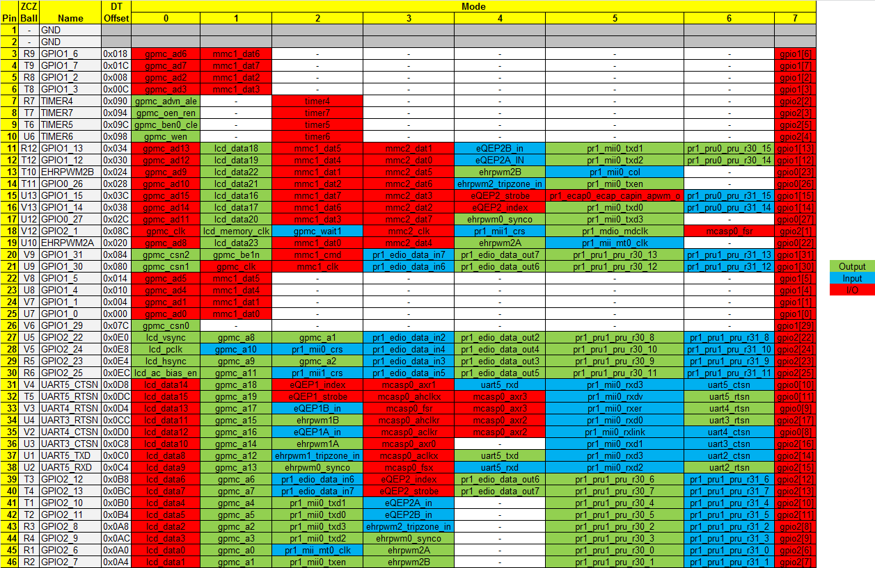
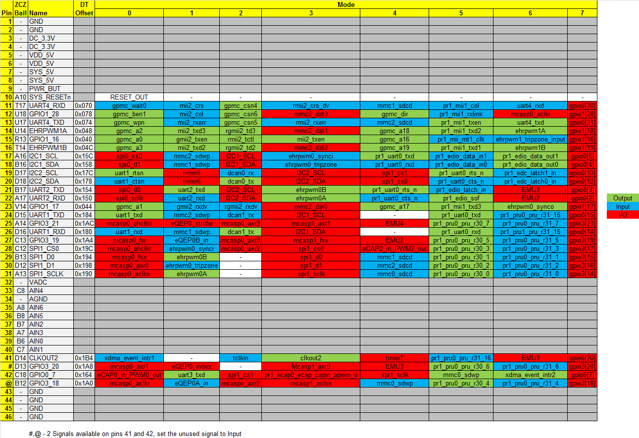
Update 20th August 2013I've created a spreadsheet to simplify the determination of register offset and mode values so you no longer have to dig through datasheets. The dcan1 signals can be found on pins P9 _24 and P9_26, both Mode 2. Use the register value worksheet to determine the correct pinmux values (Fast slew,  input for rx/output for tx, pull up, mode 2).

To find the correct register you first need to find out the name of the pins from the BBB SRM. Referring to Table 11 in the SRM, you can find the dcan1 signals are exposed on pins 24 (UART1_TXD) and 26 (UART1_RXD).

Now, diving in to the AM3359 Technical Reference Manual. In Table 9-10 (on page 759!) you can find the two registers conf_uart1_txd (0x980) and conf_uart1_rxd (0x984). These pin configuration registers start at 0x800, therefore the offset values are 0x180 and 0x184 respectively.

The detail of these registers can be found in Section 9.3.51, letting you calculate the correct values for dcan1.

Pin Slew Rate Input Pull Up Pull Up Mode Mode Mode In Hex
d_can1_tx (0x180) 0 0 1 0 0 1 0 0x12
d_can1_rx (0x184) 0 1 1 0 0 1 0 0x32


That's it for fragment@0, on to fragment@1. This section enables the CAN device. Firstly, on line 23, we identify the device we want to enable as dcan1. Then we specify that we want the device enabled by setting it's status to "okay" on line 28. Finally, we associate the pin mux created in fragment@0 with the device, line 30.

To compile this overlay, save it as BB-DCAN1-00A0.dts (the dts extension referring to a device tree source file). Then execute the following command.

 dtc -O dtb -o BB-DCAN1-00A0.dtbo -b 0 -@ BB-DCAN1-00A0.dts 

This will create the overlay binary BB-DCAN1-00A0.dtbo. If you get an error about the -@ option being unrecognised then you are likely on Ubuntu without the patched version of dtc (see here).

To use the overlay simply copy it to /lib/firmware

 sudo cp BB-DCAN1-00A0.dtbo /lib/firmware 

And execute the following (note you must be logged in as root to do this, sudo will not work!)

 echo BB-DCAN1 > /sys/devices/bone_capemgr.*/slots 

Check with dmesg to see if this worked, you should see something like this

dmesg | tail -n15
[   17.878323] init: plymouth-stop pre-start process (796) terminated with status 1
[  283.946706] bone-capemgr bone_capemgr.8: part_number 'BB-DCAN1', version 'N/A'
[  283.946892] bone-capemgr bone_capemgr.8: slot #9: generic override
[  283.946944] bone-capemgr bone_capemgr.8: bone: Using override eeprom data at slot 9
[  283.946996] bone-capemgr bone_capemgr.8: slot #9: 'Override Board Name,00A0,Override Manuf,BB-DCAN1'
[  283.947270] bone-capemgr bone_capemgr.8: slot #9: Requesting part number/version based 'BB-DCAN1-00A0.dtbo
[  283.947323] bone-capemgr bone_capemgr.8: slot #9: Requesting firmware 'BB-DCAN1-00A0.dtbo' for board-name 'Override Board Name', version '00A0'
[  283.951368] bone-capemgr bone_capemgr.8: slot #9: dtbo 'BB-DCAN1-00A0.dtbo' loaded; converting to live tree
[  283.952035] bone-capemgr bone_capemgr.8: slot #9: #2 overlays
[  283.953133] platform 481d0000.d_can: alias fck already exists
[  283.962225] bone-capemgr bone_capemgr.8: slot #9: Applied #2 overlays.
[  284.034183] CAN device driver interface
[  284.071999] c_can_platform 481d0000.d_can: invalid resource
[  284.078088] c_can_platform 481d0000.d_can: control memory is not used for raminit
[  284.084553] c_can_platform 481d0000.d_can: c_can_platform device registered (regs=fa1d0000, irq=71)

If you have something to hook up to (don't forget to go through a transceiver, or bad things will happen), you can test everything is up and working with can-utils. First, make sure you have all the relevant modules loaded.

sudo modprobe can
sudo modprobe can-dev
sudo modprobe can-raw

Get and build can-utils

svn co svn://svn.berlios.de/socketcan/trunk
cd trunk/can-utils/
make

Set up the bus speed and enable it

sudo ip link set can0 up type can bitrate 500000
sudo ifconfig can0 up

Now you can use either cansend or candump to test your bus.

Unfortunately, I've discovered my car is more rust than chassis so the track days are going to have to wait. BBB has been repurposed to other projects, more details on these coming soon...

Enabling DCAN0

Update 26th August 2013: After the comment from Marco below, I've put this section in to enable DCAN0.

To enable dcan0, you'll need an overlay similar to that for dcan1. Marco posted one below, but it seems the comment system strips angled brackets for fear of HTML tags, so here is one I made.

/dts-v1/;
/plugin/;
 
/ {
    compatible = "ti,beaglebone", "ti,beaglebone-black";
 
    /* identification */
    part-number = "dcan0pinmux";
 
    fragment@0 {
        target = <&am33xx_pinmux>;
        __overlay__ {
            dcan0_pins_s0: dcan0_pins_s0 {
                pinctrl-single,pins = <
                    0x178 0x12  /* d_can0_tx, SLEWCTRL_FAST | INPUT_PULLUP | MODE2 */
                    0x17C 0x32  /* d_can0_rx, SLEWCTRL_FAST | RECV_ENABLE | INPUT_PULLUP | MODE2 */
                >;
            };
        };
    };
 
    fragment@1 {
        target = <&dcan0>;
        __overlay__ {
             #address-cells = <1>;
             #size-cells = <0>;
 
             status = "okay";
             pinctrl-names = "default";
             pinctrl-0 = <&dcan0_pins_s0>;
        };
    };
};

We can build and install this in the same way

dtc -O dtb -o BB-DCAN0-00A0.dtbo -b 0 -@ BB-DCAN0-00A0.dts
sudo cp BB-DCAN0-00A0.dtbo /lib/firmware

However, if you try to enable dcan0 now you will get an error about the i2c pins (see Marco's comment). This is because the i2c2 pins are enabled by default and take precedence over any overlay. Before we continue I should mention that the i2c2 pins are used by the BBB to identify capes, and enable devices/pinmuxes appropriately, everything I do from here on is likely to stop any capes working!.

Another warning: This process involves modifying the default device tree binary. If you do this incorrectly, your BBB will not boot. If you're messing with the eMMC image, I can't guarantee it can be reflashed either (although I see no reason why it shouldn't be possible). You're following this guide at your own risk, if it breaks your BBB it's not my fault! I do all my hacking on an Ubuntu flashed SD card, so if it goes wrong (and it often does!) I can stick the card in my PC and undo any changes. eMMC users, continue at your own risk...

Unfortunately, we can't simply disable i2c2 with an overlay (I have tried, it crashed my BBB!). We also can't switch off the i2c2 device, because it is used by bone_capemgr and disabling it seems to make /sys/devices/bone_capemgr.*/slots disappear, meaning we can't enable overlays! So, my work around is simply to prevent the i2c2 device setting its pinmux and claiming the dcan0 pins. In this state, as far as bone_capemgr is concerned, the i2c2 pins are perpetually disconnected (but the device still exists in /dev/).

To stop i2c2 from setting its pinmux, we need to modify the default device tree binary, and to do this we need the source files. If you built your kernel from scratch you will have them lying around somewhere, but if not you can grab them from Derek Molloy's git repository (Note, I'm assuming the 3.8.13 kernel here).

git clone https://github.com/derekmolloy/boneDeviceTree.git
cd boneDeviceTree/DTSource3.8.13/

Open up am335x-bone-common.dtsi and go to line 401 (pass the -c flag to nano to show line numbers). This is the section concerning i2c2.

 nano -c am335x-bone-common.dtsi 
&i2c2 {
	status = "okay";
	pinctrl-names = "default";
	pinctrl-0 = <&i2c2_pins>;

	clock-frequency = <100000>;

	cape_eeprom0: cape_eeprom0@54 {
		compatible = "at,24c256";
		reg = <0x54>;
	};

	cape_eeprom1: cape_eeprom1@55 {
		compatible = "at,24c256";
		reg = <0x55>;
	};

	cape_eeprom2: cape_eeprom2@56 {
		compatible = "at,24c256";
		reg = <0x56>;
	};

	cape_eeprom3: cape_eeprom3@57 {
		compatible = "at,24c256";
		reg = <0x57>;
	};
};

To prevent the pinmux from being applied, simply comment out line 404

//	pinctrl-0 = <&i2c2_pins>;

Save and exit, then build with (note, you're not building the file you just edited!)

dtc -O dtb -o am335x-boneblack.dtb -b 0 -@ am335x-boneblack.dts

Before overwriting your default device tree binary, back it up

sudo mv /boot/uboot/dtbs/am335x-boneblack.dtb /boot/uboot/dtbs/am335x-boneblack.orig.dtb

Now move your new binary in to place

sudo mv am335x-boneblack.dtb /boot/uboot/dtbs/

You'll get an error about preserving permissions, you can safely ignore this.

Now reboot your BBB and the i2c2 pinmux will not be applied. Now you should be able to enable dcan0 in much the same way as dcan1. As root (not sudo!)

 echo BB-DCAN0 > /sys/devices/bone_capemgr.*/slots 

Now grab can-utils and play around with the bus (see above for dcan1).

If you plan to use dcan0 and dcan1, I believe the device driver numbering is based on the order the devices are enabled. So enable dcan0 before dcan1 so that your calls to ip, ifconfig, candump, etc... all make sense!

Posted in BeagleBone Black, Car Hacking