
The previous post in this series detailed the use of the RFM22B wireless transceivers with the BeagleBone Black (BBB). This achieves the "Wireless" part of the title, now to look at the "Servo Control" part. This post looks at using the BBBs Programmable Realtime Unit (PRU) to generate high resolution Pulse Width Modulation (PWM) signals which can be used to drive servos. For those of you not familiar with PWM servo signals, this Wikipedia page gives a basic introduction.
Enabling the PRU
Enabling the PRU system on the BBB is a little convoluted. A kernel driver already exists (uio_pruss), but this needs to be supplemented with a userspace driver which must be built from source. The PRU is coded in TIs own assembly instruction set, therefore the assembler must also be built from source. I have hidden the details of all of this inside a convenient bash script, feel free to have a look inside if you want to know the details. Firstly, grab my git repository
git clone https://github.com/omcaree/bbb-prupwm.git
cd bbb-prupwm
Now, do all the of setup with
sudo ./install_pruss.sh
You might see a few warnings which you can safely ignore, but any errors would be bad. Assuming everything went okay, we can now sort out the device tree.
I have included a device tree overlay which enables the PRU and enables all of the available PRU0 outputs (the BBB has 2 PRUs, we will only use PRU0 for this post). Before we install this, lets look at what it does.
The BBB SRM doesn't show the PRU modes for header pins, therefore to identify the output pins refer to my spreadsheet. Signals identified as pr1_pru0_pru_r30_* are outputs for PRU0 (and those identified as pr1_pru0_pru_r31_* are inputs, the naming convention will make a little more sense later). Inspection of the spreadsheet reveals the following outputs available.
| Signal | Pin | Mode | DT Offset | Pin mux value |
|---|---|---|---|---|
| pr1_pru0_pru_r30_0 | P9_31 | 5 | 0x190 | 0x05 |
| pr1_pru0_pru_r30_1 | P9_29 | 5 | 0x194 | 0x05 |
| pr1_pru0_pru_r30_2 | P9_30 | 5 | 0x198 | 0x05 |
| pr1_pru0_pru_r30_3 | P9_28 | 5 | 0x19C | 0x05 |
| pr1_pru0_pru_r30_4 | P9_42* | 5 | 0x1A0 | 0x05 |
| pr1_pru0_pru_r30_5 | P9_27 | 5 | 0x1A4 | 0x05 |
| pr1_pru0_pru_r30_6 | P9_41* | 5 | 0x1A8 | 0x05 |
| pr1_pru0_pru_r30_7 | P9_25 | 5 | 0x1AC | 0x05 |
| pr1_pru0_pru_r30_14 | P8_12 | 6 | 0x30 | 0x06 |
| pr1_pru0_pru_r30_15 | P8_11 | 6 | 0x34 | 0x06 |
*These pins are each connected to two signals, which ever signal is not being used (offsets 0x1B4 and 0x164) must be set as inputs (0x20).
The pin mux values are simply the pin mode, settings such as slew rate and pull up/down are left default. You can confirm this with the register value worksheet in the spreadsheet. The overlay pin mux is therefore
0x030 0x06  /* P8_12 to PRU output */
0x034 0x06  /* P8_11 to PRU output */
0x190 0x05  /* P9_31 to PRU output */
0x194 0x05  /* P9_29 to PRU output */
0x198 0x05  /* P9_30 to PRU output */
0x19C 0x05  /* P9_28 to PRU output */
0x1A0 0x05  /* P9_42 to PRU output */
0x1A4 0x05  /* P9_27 to PRU output */
0x1A8 0x05  /* P9_41 to PRU output */
0x1AC 0x05  /* P9_25 to PRU output */
0x1B4 0x20  /* CLKOUT2 to input as per datasheet (to enable P9_41) */
0x164 0x20  /* GPIO0_7 to input as per datasheet (to enable P9_42) */
If you're running Ubuntu, before compiling the overlay, make sure you have the patched device tree compiler. To compile, install and enable this overlay all at once, simply run
sudo ./enable_pru0_outputs.sh
PWM with the PRU
Now your BBB PRU should be set up an ready to use, so lets have a look at programming the PRU to do PWM. Note that I'm only using the 8 outputs on the P9 header for PWM, despite enabling them all in the overlay (two additional outputs exist on P8).
I should start by saying I taught myself the basics of TI's PRU assembly instruction set fairly quickly and didn't bother with macros and things, because I knew my code was going to be fairly short. I don't doubt there are far better ways of coding this, but it works which is all I want. We'll look at the PRU code first (since that's the interesting bit), then we'll look at how we run and interact with it.
PRU Code
.origin 0
.entrypoint START
#include "../include/pru.hp"

START:
// Preamble to set up OCP and shared RAM
	LBCO	r0, CONST_PRUCFG, 4, 4		// Enable OCP master port
	CLR 	r0, r0, 4					// Clear SYSCFG[STANDBY_INIT] to enable OCP master port
	SBCO	r0, CONST_PRUCFG, 4, 4
	MOV		r0, 0x00000120				// Configure the programmable pointer register for PRU0 by setting c28_pointer[15:0]
	MOV		r1, CTPPR_0					// field to 0x0120.  This will make C28 point to 0x00012000 (PRU shared RAM).
	ST32	r0, r1
// End of preamble

// Shared memory registers
//	Int 0: 		Total PWM period (number of PRU cycles)
//	Int 1-8:	Pulse width for each channel (number of PRU cycles)
LOOP1:										// Outer loop repeats everything at PWM period
	LBCO	r0, CONST_PRUSHAREDRAM, 0, 36	// Load in registers from shared memory
	SET		r30.t0							// Turn on all output channels for start of cycle
	SET		r30.t1
	SET		r30.t2
	SET		r30.t3
	SET		r30.t4
	SET		r30.t5
	SET		r30.t6
	SET		r30.t7
LOOP2:										// Inner loop to handle channels
		SUB		r0, r0, 1					// Subtract one from each register
		SUB		r1, r1, 1
		SUB		r2, r2, 1
		SUB		r3, r3, 1
		SUB		r4, r4, 1
		SUB		r5, r5, 1
		SUB		r6, r6, 1
		SUB		r7, r7, 1
		SUB		r8, r8, 1
		QBNE	SKIP1, r1, 0				// Compare each register with zero
		CLR		r30.t0						// If zero then turn off the corresponding channel
SKIP1:										// Otherwise skip that channel (leaving it high)
		QBNE	SKIP2, r2, 0
		CLR		r30.t1
SKIP2:
		QBNE	SKIP3, r3, 0
		CLR		r30.t2
SKIP3:
		QBNE	SKIP4, r4, 0
		CLR		r30.t3
SKIP4:
		QBNE	SKIP5, r5, 0
		CLR		r30.t4
SKIP5:
		QBNE	SKIP6, r6, 0
		CLR		r30.t5
SKIP6:
		QBNE	SKIP7, r7, 0
		CLR		r30.t6
SKIP7:
		QBNE	SKIP8, r8, 0
		CLR		r30.t7
SKIP8:
		QBEQ	LOOP1, r0, 0			// If cycle register is empty, restart
		QBA		LOOP2					// Total of 19 statements per cycle, 95ns
	HALT								// Halt the processor (although we will never get here...)
- Lines 20-32 are shamelessly stolen from the example codes packaged with the drivers. They deal with setting up the PRU memory and interrupts
- Line 37 defines the start of the useful code, it is a label identifying the top of the main loop (imaginatively named LOOP1). This loop is responsible for repeating the PWM pulses at a fixed frequency
- Line 38 uses LBCO to load 9 4-byte registers (36 bytes) from shared memory in to the PRUs internal registers (r0-r8). These registers represent the total PWM period and the period of the 8 output channels (all of which are in units of PRU cycles, more on this later)
- Lines 39-46 use SET to set the individual bits of register r30 high to start the PWM signal. These bits correspond directly to the output pins identified earlier (e.g. setting the r30.t0 toggles the pr1_pru0_pru_r30_0 signal high). This could be done with a single operation (setting r30 to 0b11111111), but I opted to be verbose to make things easier to follow/debug.
- Line 47 starts another loop which handles the setting of outputs low when their periods have elapsed.
- Lines 48-56 use SUB to decrement each of the period registers by 1
- Lines 57-80 perform the same comparison operation on all channels. Firstly QBNE is used to branch to label SKIPx if register rx is not equal to 0, otherwise execution simply continues and invokes CLR to set the corresponding output register bit low (that is, its period has elapsed). The net effect (for channel 1) of this is identical to an if statement:
if (r1 == 0) {
     clear(r30.t0);
}
- Line 81 uses QBEQ to start the next PWM pulse (from LOOP1) when the total PWM period has elapsed (i.e. r0 == 0) .
- Line 82 continues the current PWM pulse indefinitely (from LOOP2) with QBA. This statement is only reached if the previous QBEQ is not executed (therefore we continue the current pulse if we haven't already reset for the next pulse).
- Line 83 halts the PRU, but this statement is never actually reached because the QBA above will always branch to LOOP2
PRU Timing
The above description spent a lot of time referring to PWM and channel periods, I should probably explain this in more detail. The PRU has limited mathematical capabilities (unless you code them yourself), so you want to offload as much calculation as possible to the host process. For PWM generation, this means you don't pass the PRU parameters such as pulse time (e.g. 1500us), frequency (e.g. 50Hz) or duty cycle (e.g. 20%), because all of these require multiplication or division operations to arrive at a number of loops value. Instead, we simply pass the PRU this number of loops directly. To calculate this value, the host process needs to know how long it takes the PRU to execute a single loop. Being a realtime unit, independent of the CPU, we can calculate this loop time by multiplying the number of statements by the time it takes to execute a single statement.
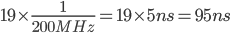
To determine the number of statements, we first ignore the conditional statements which are usually skipped (the clearing of output bits). This will introduce a minor inaccuracy in our timing, but as these statements only execute 8 times (once per channel) in tens of thousands of loops, it's a minor effect. Next we count up the remaining statements executed within the inner loop (between LOOP2 on line 47 and QBA on line 82). The counted statements are highlighted in the listing above, 19 statements in total. Each statement takes a single clock cycle to execute and the PRU clock is 200MHz, therefore the time taken to execute a single PRU cycle is
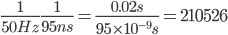
To generate a 50Hz signal (for standard RC servos), the PRU PWM period register (r0) should be set to
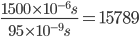
And to set the first channel to 1500us (centre position of standard servo), the channel period register (r1) should be set to
Now we have the PRU code and know how to calculate its register values.
Running the example
I've written some C++ classes for interfacing with the PRU (src/pru.cpp and include/pru.cpp) and handling the PWM calculations (src/pruPWM.cpp and include/pruPWM.cpp).
The PRU class is largely based on the example codes bundled with the drivers. It uses the functions from the prussdrv library to set up the PRU, run code and interact with the shared memory. It does not currently support host or PRU interrupts, but I'm working on this for another project.
The PRUPWM class handles the calculation of PWM periods as mentioned above and passes them on to the PRU class.
Here is the example code from the repository, it demonstrates the use of the PRUPWM class to control the channels.
#include <signal.h>
#include "pruPWM.h"

// Some globals
PRUPWM *myPWM;
bool running;

// Default all channels (handy way of quitting with known output state)
void setDefaults(int signal = 0) {
	for (int i = 0; i < 8; i++) {
		myPWM->setChannelValue(i,1500000);
	}
	running = false;
}

// Entry point
int main() {
	// Initialise PRU PWM
	myPWM = new PRUPWM();

	// Default all channels
	setDefaults();

	// Register 'setDefaults' as interrupt handler to catch Ctrl+C
	signal(SIGINT, setDefaults);

	// Start the PRU
	myPWM->start();

	// An example loop
	running = true;
	int pwm0 = 1000000, pwm7 = 2000000;
	int step = 100;
	while (running) {
		myPWM->setChannelValue(0,pwm0);
		myPWM->setChannelValue(7,pwm7);
		pwm0 += step;
		pwm7 -= step;
		if (pwm0 >= 2000000 || pwm0 <= 1000000 || pwm7 >= 2000000 || pwm7 <= 1000000) {
			step *= -1;
			usleep(1000000);
		}
		usleep(100);
	}
}
- Lines 29-34 is a useful little function to default all the outputs to 1500us (note that setChannelValue takes its argument in ns)
- Line 39 initialises the class. The constructor takes an optional argument which is the PWM frequency in Hz (50 is default)
- Line 42 defaults all the channels (do this before starting the PRU or bad things might happen to your servos!)
- Line 45 registers the setDefault function to be called when Ctrl+C is pressed
- Line 48 starts the PRU code
- Lines 51-64 cycles channel 0 and channel 7 up and down (in opposite directions), pausing at the extents
To build the example simply run
make
In addition to compiling the example code, make will use the PRU assembler we built and installed earlier (automatically) to compile the PRU code to pwm.bin, This PRU binary must reside in the same folder as the executable or you'll get a seg fault.
All PRU related code must be run with root privileges in order to access the PRU device and memory space. So run the example with
sudo ./prupwm
Here is a video of the example in action...
Some of you may be wondering how I'm able to drive 5V servos with 3.3V PWM signals. It turns out that the vast majority of 5V devices are perfectly happy with 3.3V signals as they tend to recognise a transition from low to high (and vice versa) at around 2.5V. If I was going to make a product out of this, I would go to the effort of shifting the levels up to 5V as this will provide greater robustness to noise. But for this little prototype it works just fine. Note that I said 5V devices are happy with 3.3V signals, the reverse of this is usually not the case, do not connect 5V signals directly to your BBB or you'll damage it!
Before the next (and final) installment, I have included an update to this post concerning the implementation of a failsafe within the PRU code. The final installment (coming soon...) will use the BBB ADCs to generate the position command for the servos, send this wirelessly using the RFM22Bs and then control the servos on a second BBB, thus achieving the goal of wireless servo control!
Hi,
Can I see gpio modes indepenently ? I would like still to use I2C busa at 19,20 P9 header.
Which channels output to which gpio ?
Thanks,
Mateusz