
I'm sure this exists on the web somewhere, but after 30s of Googling I couldn't find it, so I've put together a comprehensive spreadsheet for BBB pinmuxing.
Firstly, I have updated Tables 10 and 11 from the BBB SRM to include:
- All pin modes from the AM335x Datasheet (SRM doesn't show PRU modes)
- Colour coded modes depending on whether they are Input, Output or I/O
- Included the Device Tree Offset values needed for creating pin muxes in a Device Tree Overlay
Note that I have kept the pin names consistent with the SRM, despite this being at odds with the datasheet!
Here are some images of the tables for quick reference
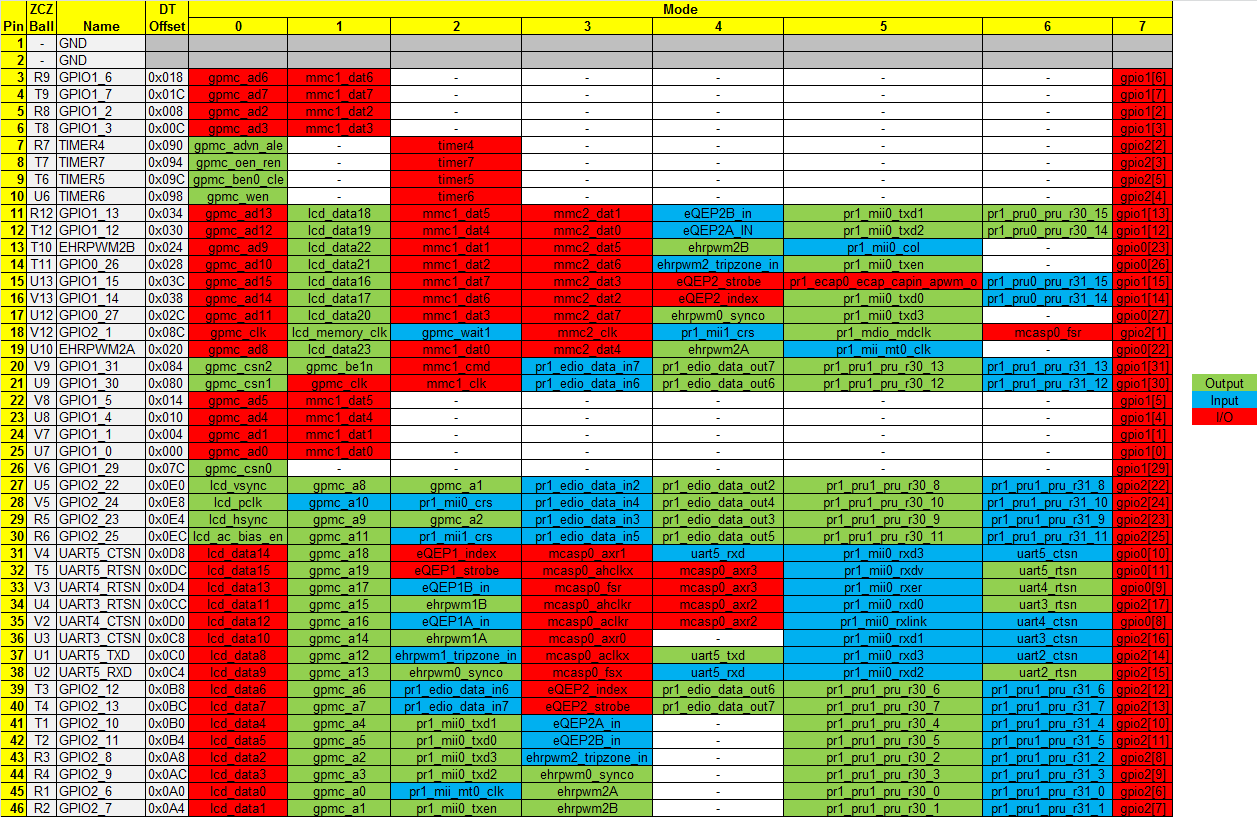 P8 Header P8 Header |
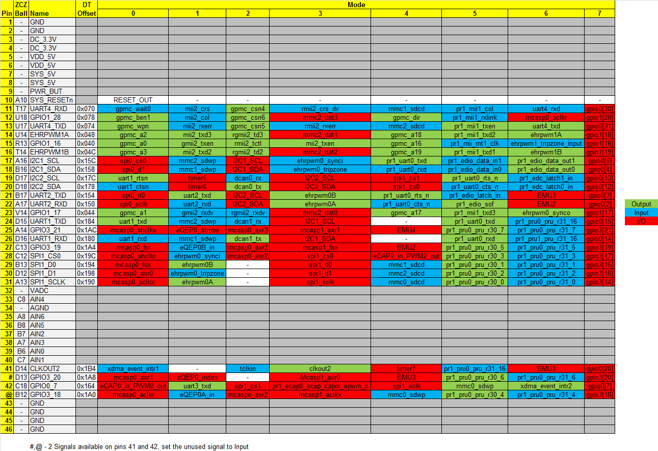 P9 Header P9 Header |
|---|
I've also included a sheet which lets you calculate the required register value for pin muxing.
Spreadsheet is available to download here.
FYI, on B12, you have "mcaspo_axr2". It should be "mcasp0_axr2" with a zero instead of the letter o. On D13, you have "Mcasp1_axr0". I think that should be "Mcasp1_axr0" with a lower case m.
FYI, according to the Beaglebone Black Rev C schematic, both processor pins R13 and T13 are wired to P9 pin 15, in the same way that two processor pins are wired to P9 pins 41 and 42.